The pictures show the pilot plant installation.
Click on the images to enlarge.
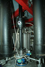
Picture # 1 shows the two cylinders (black) on each side of the inline mixer, which has a small filling cylinder, attached to its top. Behind is the inline heat exchanger.
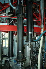
Picture #2 shows 3 large cylinders which are similar to the described push rod cylinders; in between them the inline heat exchanger.
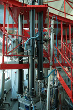
Picture # 3 shows a large view of the pilot plant set-up.